Other major product lines include tension brakes and controls available from a single manufacturer along with sensors and.
Warner electric actuator wiring diagram.
The first generation of general purpose actuators were developed for remote push button control of accessory drives on.
Collection of linear actuator wiring diagram.
A wiring diagram is a streamlined standard photographic representation of an electric circuit.
It reveals the components of the circuit as streamlined shapes as well as the power and also signal links in between the devices.
A wiring diagram is a simplified standard photographic representation of an electric circuit.
Warner electric offers the broadest selection of industrial clutches brakes controls and web tension systems available from a single manufacturer.
580a332 electric linear actuator wiring diagram library ms 0983 12v abz free pneumatic and actuators valve automation limitorque l120 collection warner c10594 color code control base website umldiagramtypes magentaproduction fr for controls pqs manualzz fff54.
Connect the negative terminal of the power supply to the t3.
Warner linear electric actuators and controls.
Warner electric engineers utilize the latest materials and manufacturing technologies to design long life easy to use clutches and brakes that provide improved accuracy and repeatability.
Warner linear h track actuators.
Here s the diagram describing a process.
Warner linear electric actuators and controls.
Linear actuators are ideally suited for intermittent duty cycle applications requiring lift lower push pull positioning sorting opening or adjusting on both in plant or mobile applications.
By admin march 13 2018.
Our linear product line offers linear actuators and controls.
Wiring diagram pictures detail.
Warner linear electric actuators and controls.
Warner linear h track actuators.
Warner electric parts offers products from the leading manufacturer and supplier of industrial power transmission products that includes clutches and brakes.
It shows the components of the circuit as streamlined shapes and the power and signal links in between the devices.
Warner electric engineers utilize the latest materials and manufacturing technologies to design long life easy to use clutches and brakes that provide improved accuracy and repeatability.
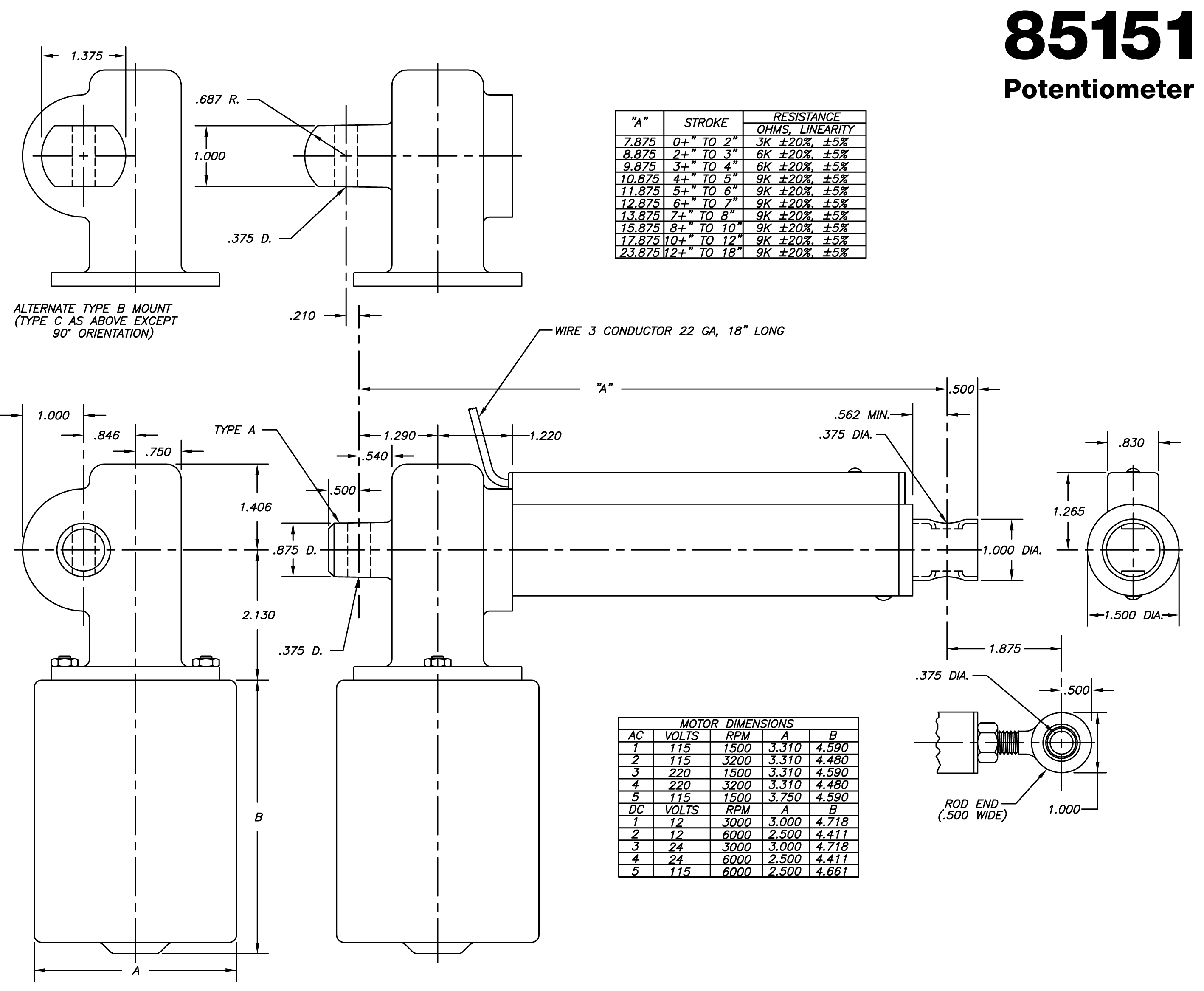
Warner electric linear actuators.
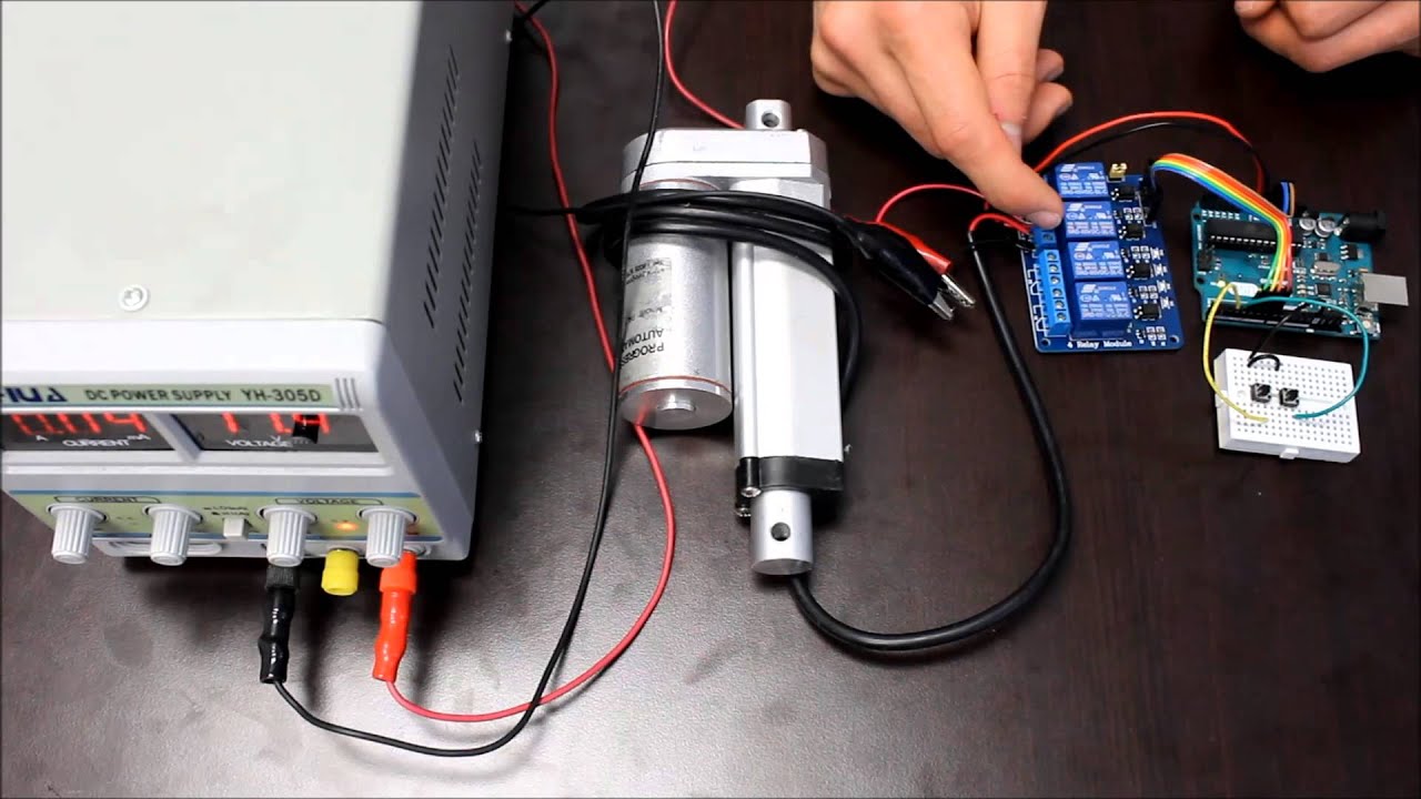
Follow the instructions described in the linear actuator wire diagram.
Connect terminals number 3 and 4.
Wiring diagram in our example we use the rocker switch.
It has 6 terminals you should connect to wire up the actuator.
Warner electric actuator wiring diagram.
Warner linear actuator wiring diagram warner linear actuator wiring diagram application wiring diagram u2022 rh diagramnet today linear actuator controller kit pump solenoid schematic.